
TM
5-3431-203-15
(2) Secure the control panel to the frame
(3) Install the high frequency panel as-
sembly (para 3-27).
(4) Install the welder top and housing
4-20. Control Rheostat
a. Removal.
(1) Remove the welding machine top and
housing (para 3-26).
(2) Remove the high frequency panel as-
sembly ( para 3-27).
(3) Loosen the control panel from the
frame (para 4-16).
(4) Refer to figure 4-4 and remove the
control rheostat.
b. Testing.
(1) Connect an ohmmeter to the two
outer terminals of the rheostat and
s e t the meter on RXI scale. The
reading should be 32 ohms. If the
reading is more or less than 32 ohms,
replace the rheostat.
(2) Connect an ohmmeter to the center
terminal and either outside terminal
of the rheostat. Set the meter on
the RX1 scale. Turn the rheostat in
either direction until it stops, then
t u r n it in the opposite direction
s l o w l y and evenly until it stops
The indicator on the meter
again.
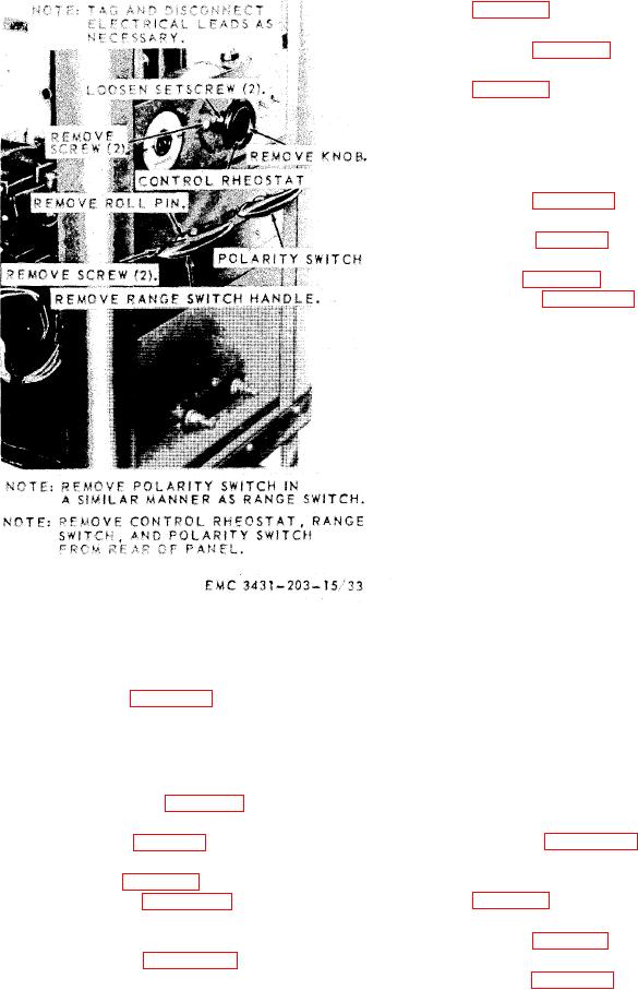
Figure 4-4. Range switch, polarity switch, and
should increase or decrease evenly
control rheostat, removal and installation.
according to the speed in which the
(4) Install the welding machine top and
rheostat is turned. If the meter in-
housing (para 3-26).
d i c a t o r does not function as de-
scribed, replace the rheostat.
4-19. Polarity Switch
Note. Make sure the ohmmeter used for
a. Removal.
the above tests is in proper working condi-
(1) Remove the welding machine top
tion.
and housing (para 3-26).
c. Installation.
(2) Remove the high frequency panel as-
(1) Refer to figure 4-4 and install the
sembly ( para 3-27).
control rheostat.
(3) Loosen the control panel from the
(2) Secure the control panel to the frame
frame (para 4-16).
(4) Refer to figure 4-4 and remove the
(3) Install the high frequency panel as-
polarity switch.
sembly (para 3-27).
b. Instillation.
(4) Install the welding machine top and
(1) Refer to figure 4-4 and install the
housing (para 3-26).
polarity switch.