TM 5-6115-586-34
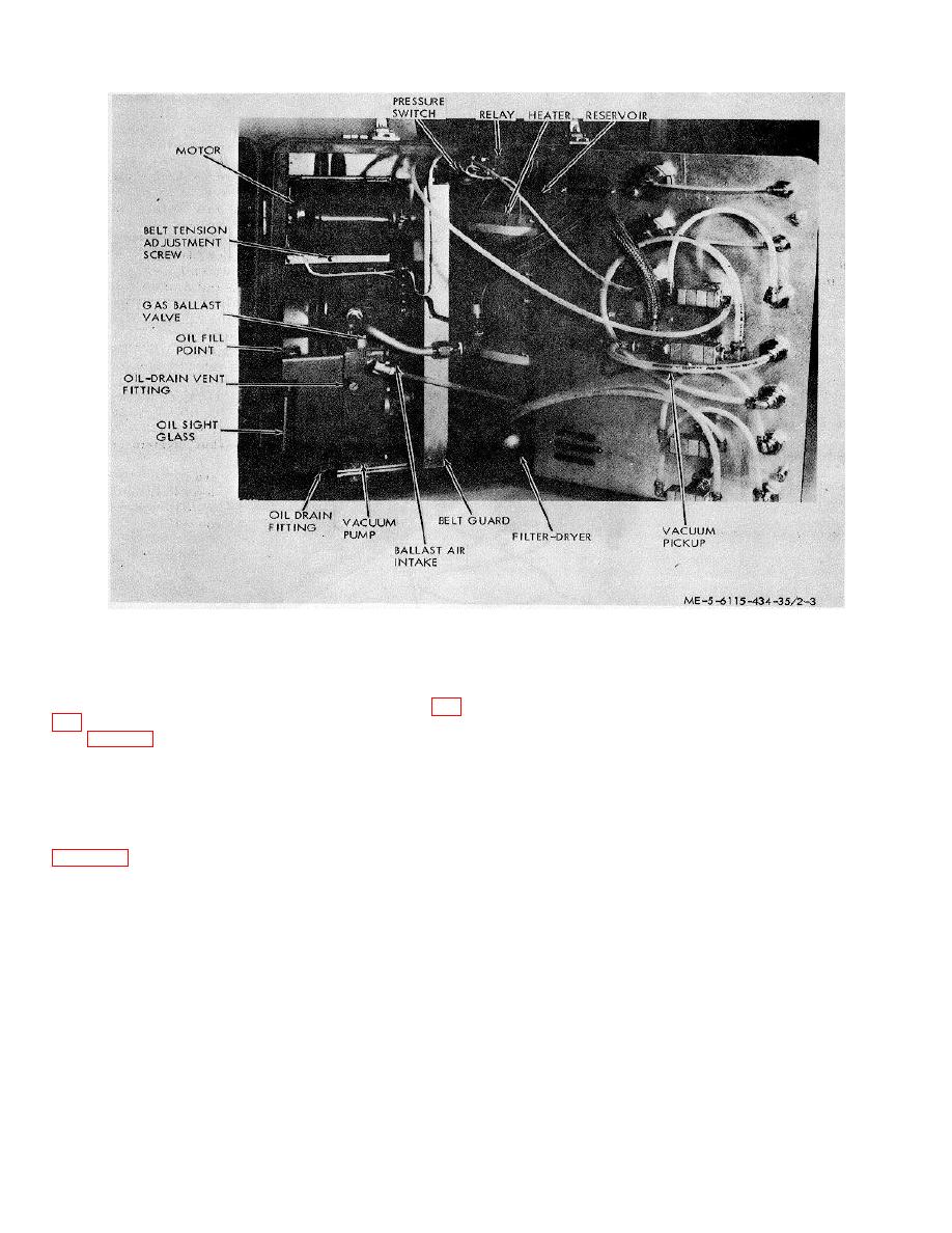
Figure 2-4. Refrigeration service unit internal details.
connection at service valve and
9. Place heater vacuum pump switch on
repeat
the
purge
procedure
service unit in OFF position. Place power switch on
outlined above.
service unit in down position. Close gas ballast valve (fig.
4 Tap service valve on power plant receiver
to dislodge any air pockets.
V4 (fig. 2-2) on service unit. Remove vacuum hoses
from power plant refrigeration system connecting points
5 Fill beaker with oil, Military Specification
and from service unit.
MIL-L-6085A, enough to charge system and enough left
over to prevent entrance of air into charging hose.
(c) Refrigeration system charging procedure. To
charge the power plant refrigeration system, first
6 Crack
service
valve
on
power
plant
evacuate the system as described in paragraph (b) above.
receiver.
When system has been properly evacuated, refer to
7 Charge
system
with
oil,
Military
Specification MIL-L-6085A.
1 Loosely connect oil charging hose (part. of
refrigeration system service unit) to service valve on
8 Close
service
valve
on
power
plant
power plant refrigerant receiver.
receiver.
2 Fill beaker (part of refrigeration system
9 Remove oil charge hose from power plant
service unit) with oil, -Mil Spec MIL-L-6085A, enough to
service valve.
purge all air from oil charging hose.
10 Place heater vacuum switch on service unit
3 Tighten oil charging hose fitting at service
in HEATER position and place power switch to ON
valve on power plant refrigerant receiver while oil is
position.
bleeding from connection.
11 Allow service unit refrigerant reservoir
heater to stabilize pressure at 70 10 psig
Note
If any air bubbles are observed in
oil in the oil charging hose, loosen
2-10


