
TM 5-3431-203-15
Section X. GAS AND WATER SOLENOID VALVES
3-48. General
The gas solenoid valve is used when the op-
erator is performing inert-gas welding. The
solenoid valve is operated electrically through
the timer control. The waker solenoid valve is
used when a water-cooled torch is used. The
water solenoid valve is operated electrically
through the timer control.
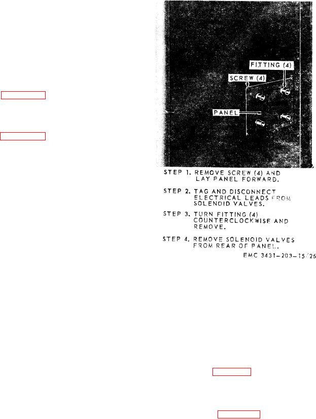
3-49. Gas Solenoid Valve
Refer to figure 3-17 and remove and in-
stall the gas solenoid valve.
3-50. Water Solenoid Valve
Refer to figure 3-17 and remove and install
the water solenoid valve.
and installation.
Section XI. VENTILATING-COOLING SYSTEM
3-52. Fan, Motor, and Guard Assembly
3-51. General
a. Removal.
The welding machine is cooled by a fan mo-
tor assembly which operates from the acces-
(1) Remove the welding machine top and
sory power transformer. It has four aluminum
housing (para 3-26).
blades which pull the air through the welder
(2) Disconnect the motor leads from the
and out the back, The ballast resistors are
top and bottom terminals of the ac-
mounted on the fan guard so that they can
cessory transformer.
be cooled by the air as it passes through
(3) Refer to figure 3-1 and remove the
them. TO make any repairs on the motor fan
fan, mater, and guard as a complete
blade, or guard, the complete assembly must
unit.
be removed.