Home
Download PDF
Order CD-ROM
Order in Print
Figure 4-7. Control rectifiers, removal and installation.
Figure 4-9. Resistors, removal and installation.
TM-5-3431-225-15 Welding Machine ARC: General and Inert Gas Shielded Transformer; 300 AMP; 5 to 460 AMP AC: 5 to 350 AMP DC FSN 3431-620-0858 Manual
Page Navigation
50
51
52
53
54
55
56
57
58
59
60
TM
5-3431-225-15
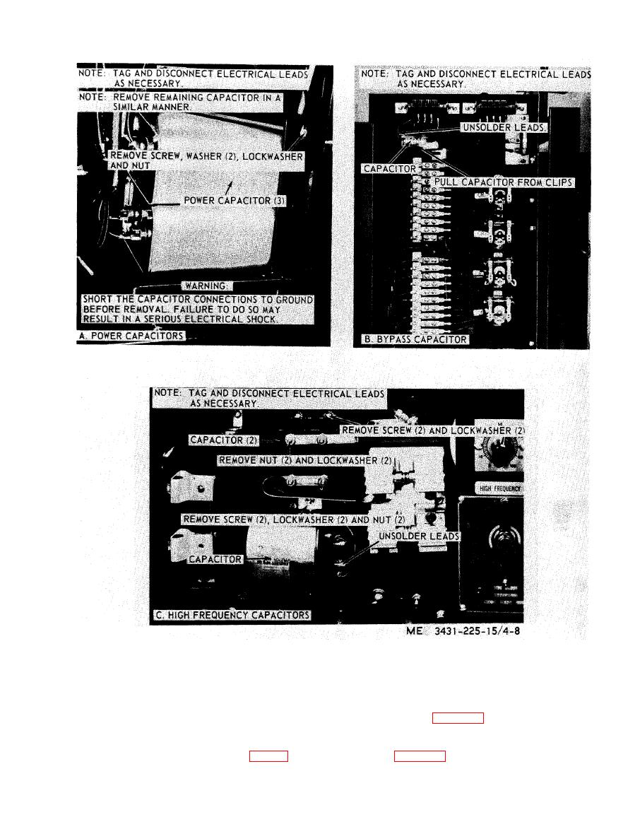
Figure
4-8.
Capacitors,
removal
and
installation.
b.
Testing.
Connect
an
ohmmeter
to the
resis-
C
.
Installation.
(1)
Refer
to
figure
4-9
and
install
the
re-
tor
leads
and
check
the
resistance
.
The meter
sistors.
leading
must
conform
with the
resistor
values
(2)
Install
the
top
and
sides
on the
welding
shown
on the
schematic
diagram
(fig.
1-4).
machine
(para
3-26).
4-11