
(3) Push idler regulator rod (fig. 3-10)
sensitivity screw and turn head of pin c1ock-
toward carburetor on pin in full throttle posi-
wise to maximum position. Tighten locknut.
tion.
(2) Adjust lenth of governor rod by
(4) Operate welding machine under load
screwing ball joint housing along rod until the
and set speed adjusting' screw to obtain 1400
rod just fits between arm on governor shaft
rpm, (1800 rpm for Model LEB 300).
in straight position and throttle shaft clamp
(5) Securely lock adjusting screw.
is in maximum clockwise position.
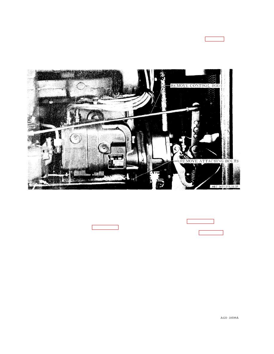
Figure 3-14. Engine speed governor, removal and installation.
(1) Remove and install choke cable from
3-29. Fuel Filter
a. Removal and Installation. Remove and
carburetor as illustrated in figure 3-10.
install fuel filter as illustrated in figure 3-15.
(2) Remove and install choke control
b. Cleaning and Inspection.
from control panel illustrated in figure 2-2.
(1) Clean filter bowl and filter with a
b. Cleaning and Inspection.
clean, lint-free cloth.
(1) Clean cable with an approved solvent.
(2) Inspect for cracks, breaks or other
Dry thoroughly.
damage. Replace damaged parts.
(2) Inspect cable for kinks or breaks. Re-
place cable if damaged.
3-30. choke Control
a. Removal and Installation.
Section X. ENGINE ELECTRICAL SYSTEM
plug cables. The starting circuit consists of a
3-31. General
Two basic electrical circuits comprise the elec-
24 volt starter which is connected to two 12
trical system. They are the ignition circuit
volt batteries, a generator, regulator and am-
and the starting circuit. The ignition circuit
meter. The starter switch is mounted on the
consists of a magneto mounted on the right
control panel and is electrically connected to
front of the engine, spark plugs and spark
the solenoid mounted on the starter.
46
