
0040 00
TM 1-4920-445-13&P
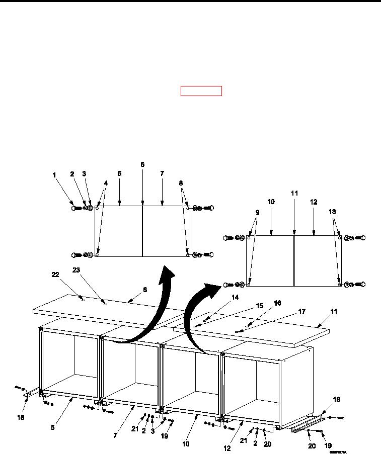
INSTALLATION CONTINUED
SHELF CABINET (A), 4 DRAWER CABINET (A), 6 DRAWER CABINET (B), 4 DRAWER CABINET (C), AND 4
DRAWER CABINET (D) (1036859) CONTINUED
16. Install four bolts (Figure 3, Item 21), eight lat washers (Figure 3, Item 22), four lock washers (Figure 3, Item
3), and four nuts (Figure 3, Item 23) attaching two cabinet brackets (Figure 3, Item 20) to four drawer cabinet
(A) (Figure 3, Item 24) and four drawer cabinet (D) (Figure 3, Item 15).
17. Install hardware attaching shelf cabinet (A) (Figure 3, Item 1), four drawer cabinet (A) (Figure 3, Item 24), six
drawer cabinet (B) (Figure 3, Item 9), four drawer cabinet (C) (Figure 3, Item 8), and four drawer cabinet (D)
(Figure 3, Item 15) to shelter loor and wall IAW WP 0041 00, Cabinets (A) and (B) Hardware, INSTALLATION.
18. Install drawers, slides, and shelves as necessary IAW Drawers, Slides, And Shelves, INSTALLATION.
19. Install kick plate IAW Kick Plate, INSTALLATION.
INSPECTION OF INSTALLED ITEMS
4 DRAWER CABINET (A), 6 DRAWER CABINET (B), 4 DRAWER
CABINET (C), AND 4 DRAWER CABINET (D) (SC4920-99-B70)
Figure 4.
Cabinet (A), Cabinet (B), Cabinet (C), and Cabinet (D) (SC4920-99-B70).
1.
Inspect cabinet assembly and work surface (Figure 4) for damage. Replace as necessary.
0040 00-8