
TM 1-4920-434-13&P
FIELD MAINTENANCE
MACHINE AND WELDING SHOP SHOP
MAINTENANCE INSTRUCTIONS FOR DOOR LOCK TABS
INITIAL SETUP:
Materials/Parts (cont.)
Tools and Special Tools
Disc Grinder (WP 0073 00, Table 2, Item 101 )
Tan 686 (WP 0079 00, Item 8)
Drill Set, Twist (WP 0073 00, Table 2, Item 102 )
Personnel Required
General Mechanics Tool Kit
CMF 15 Series (1)
(WP 0073 00, Table 2, Item 104 )
CMF 44-B Welder (1)
Hand Yoke Riveter (WP 0073 00, Table 2, Item 105 )
References
Paint Brush (WP 0073 00, Table 2, Item 107 )
Portable Electric Drill (WP 0073 00, Table 2, Item 108 )
TM 1-1500-204-23
TM 43-0139
Materials/Parts
Equipment Condition
Polysulide Sealant (WP 0079 00, Item 5)
Primer, Coating (WP 0079 00, Item 6)
Functional
INSPECTION OF INSTALLED ITEMS
DOOR LOCK TABS
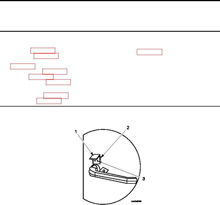
Figure 1.
Door Lock Tabs.
1.
Inspect door lock tabs (Figure 1, Item 1) for broken or cracked welds (Figure 1, Item 2).
2.
Ensure rivets (Figure 1, Item 3) are secure.
3.
Replace door lock tabs (Figure 1, Item 1) if damage is detected.
0062 00-1