
TM 1-4920-434-13&P
FIELD MAINTENANCE
MACHINE AND WELDING SHOP
MAINTENANCE INSTRUCTIONS FOR PLASMA CUTTER
INITIAL SETUP:
Personnel Required
Tools and Special Tools
CMF 15 Series (1)
Electrical Repairers Tool Kit
(WP 0073 00, Table 2, Item 103 )
Equipment Condition
General Mechanics Tool Kit
Functional
(WP 0073 00, Table 2, Item 104 )
Multimeter (WP 0073 00, Table 2, Item 106 )
TEST AND INSPECTION
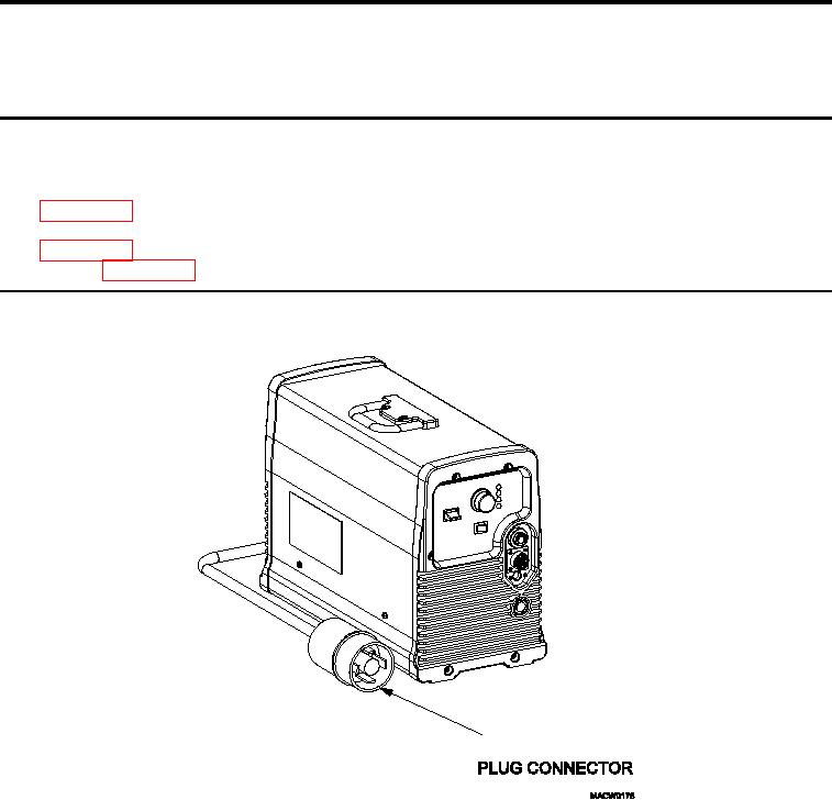
CONNECTOR PLUG
Figure 1.
Plasma Cutter Plug Connector.
With 240V connector plug unplugged, visually inspect 240V connector plug (Figure 1) for any damage that could
possibly cause an electrical hazard.
0049 00-1