
TM 1-4920-434-13&P
0042 00
INSPECTION OF INSTALLED ITEMS
SHELF CABINET (C)
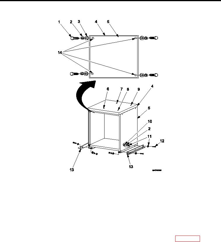
Figure 4.
Cabinet (C) .
1.
Inspect cabinet assembly and work surface (Figure 4) for damage. Replace as necessary.
2.
Inspect all cabinet assembly hardware (Figure 4, Item 1, 2, 3, 10, 11, and 12) for rust, cracks and rounded
heads. Replace as necessary.
REMOVAL
SHELF CABINET (C)
1.
Remove kick plate IAW Kick Plate, REMOVAL.
2.
Remove drawers, slides, and shelves as necessary IAW Drawers, Slides, And Shelves, REMOVAL.
3.
Remove hardware attaching shelf cabinet (C) (Figure 4, Item 5) to shelter loor IAW WP 0043 00, Cabinets
(C), (D), and (E) Hardware, REMOVAL.
4.
Remove four lag bolts (Figure 4, Item 1), four lock washers (Figure 4, Item 2), and four lat washers (Figure 4,
Item 3) detaching work surface (Figure 4, Item 4) from shelf cabinet (C) (Figure 4, Item 5).
5.
Remove work surface (Figure 4, Item 4) from top of shelf cabinet (C) (Figure 4, Item 7).
6.
Remove four bolts (Figure 4, Item 12), eight lat washers (Figure 4, Item 11), four lock washers (Figure 4, Item
2), and four nuts (Figure 4, Item 10) detaching two cabinet brackets (Figure 4, Item 13) from shelf cabinet (C)
(Figure 4, Item 5).
0042 00-7