
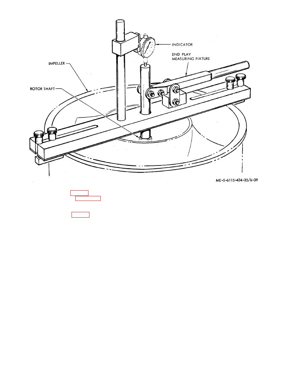
Figure 6-14. End play measurement.
Coat E42GP15 mixed equal parts by volume with
(6) Remove end bell (23, fig. 6-7) and connect electrical
Catalyst V66KP15) and air-dry for 15 to 30 minutes;
wiring in accordance with figure 6-9. Make electrical
then bake at 150to 175F (65.6to 79.4 C) for one
connections, using solder (Federal specification QQ-S-
571, Type SN60WRAP2).
hour.
(7) Reinstall end bell (23, fig. 6-7), discs (1, 12, 13) and
e.
Installation.
Refer to TM
6-115-586-12 for
washer (10). Install washer (10) with tang ends against
recirculating fans installation instructions.
bearing outer race.
(8) After assembly, paint end of rotor (26) shaft, hex
hole in shaft, and nut (18) with one coat of primer (Cati-
Section V. MOTOR DRIVEN TUBE AXIAL FAN (CONDENSER)
b. Disassembly.
6-9. General
(1) Disassembly according to sequence of item
This motor driven fan consists essentially of a cylindrical
numbers I through 30 assigned to exploded view (fig. 6-
housing assembly, a motor rotor, and end bell assembly,
15) observing the following.
a fan fairing, and a thermal protector. The housing
(2) Do not remove plates (2,3), or label (4)
assembly includes a motor stator. The fan is used to
unless required after inspection, Unsolder -wires from
force the flow of ambient cooling air through the
connector (5).
condenser of the air- conditioning system.
a. Removal. Refer to TM 5-6115-586-12 for
condenser fans removal instructions.
6-25
