
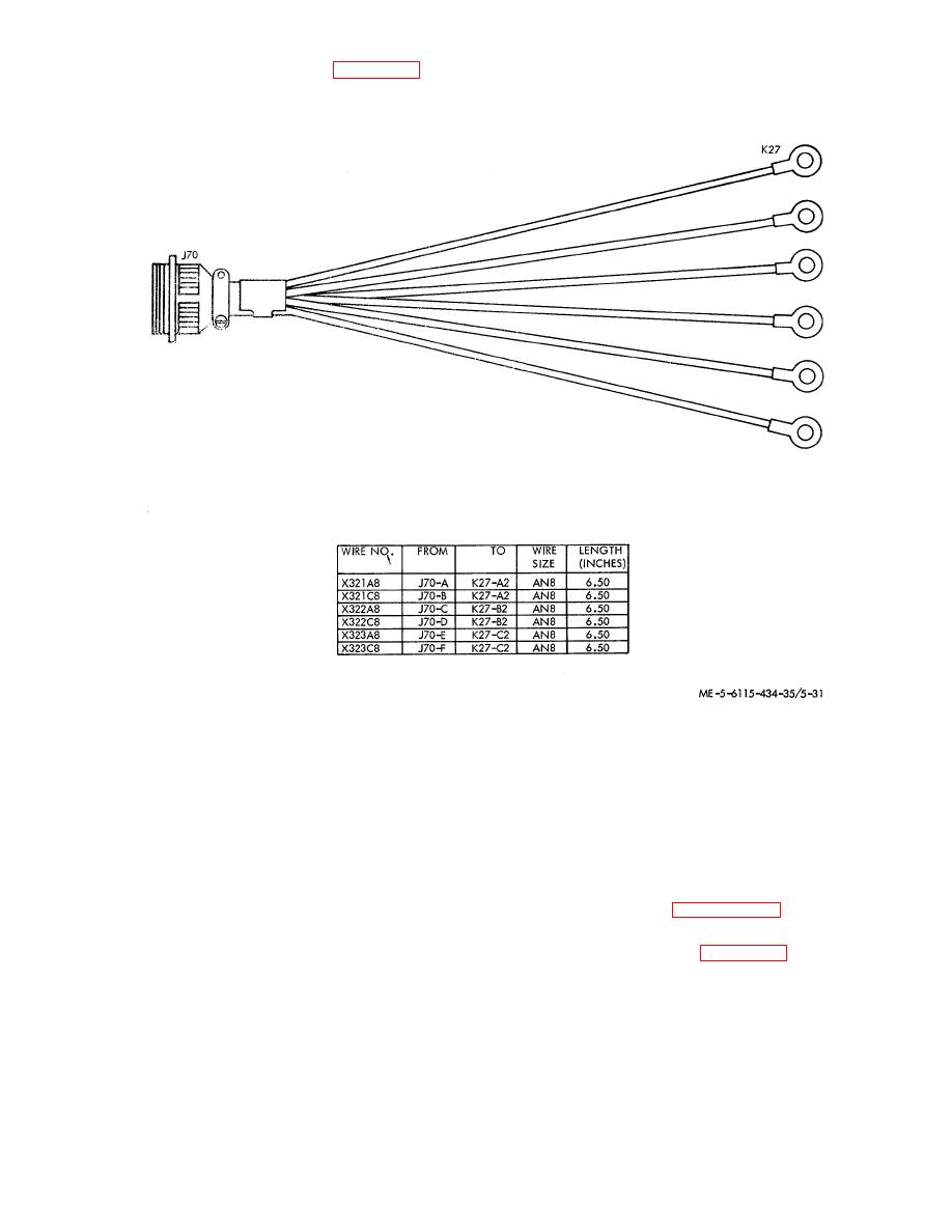
(11) Refer to wire run chart in figure 5-32 and
check continuity of individual wires in the remote power
wire harness assembly.
Figure 5-32. Remote power wire harness assembly.
compressors wire harness assemblies and recirculating fans
d. Repair and Replacement.
wire harness assembly where they shall be installed at two
(1) Replace all parts that are damaged beyond
inch intervals. Cable straps shall also be installed at all cable
simple repair; replace all missing or defective hardware.
breakouts.
Replace damaged nut plates or loose rivets on the panel.
e. Reassembly and Installation. Refer to TM 56115-586-
(2)
Repair wire harness assemblies as follows:
12 for reassembly and installation instructions.
(a) Disassemble
the
wire
harness
5-28. Auxiliary Power Tray Assembly
assemblies only as required for repair or replacement.
for removal instructions.
(b) Solder connections shall be made in
accordance with MIL-S-6872 using solder Type SN60WRP2
per Fed Spec QQ-S-571.
the auxiliary power tray assembly as follows: (I) Disconnect
leads 'of 400 Hz auxiliary power wire harness (4) from relays
(c) Replace defective wires with wire in
K43A and K43B (27). and from thermal relays S37A, S37C,
accordance with MIL-W-5086, Type II.
Wire size and
S38A. and S38C (26).
approximate length in inches is provided in applicable wire run
charts.
(d) If self-clinching cable straps are
removed to facilitate repairs, install new cable straps at three
inch intervals on all wire harness assemblies except
5-43
