
POST-FLOW TIMER are normally 30 second timers.
to increase or decrease the intensity of the spark
jump.
The SPOT ARC TIMER is normally a 6 second timer.
Set the timers according to the following procedures.
Note. The distance the spark jumps will increase as the
tungsten becomes heated and will vary also with the cable length,
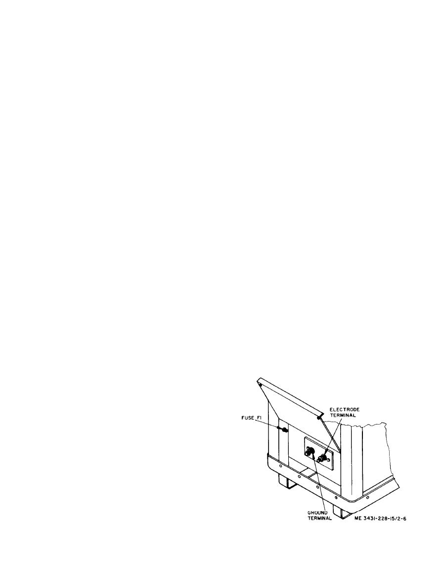
(1) Unlock and open the drawer.
base metal type, etc.
(2) Adjust the applicable timers by setting the
(5) Set CONTACTOR switch for PANEL CON-
dial to the desired seconds of delay time. Refer to
TROL or REMOTE RECEPTACLE control as de-
torch manual for settings.
sired to affect start/stop control of welding power
(3) For timers not being used, set controls as
output.
follows:
Note. When set in the PANEL CONTROL position it allows
(a) If PRE-FLOW TIMER is not to be used,
the POWER switch to directly control the ON and OFF of welding
set dial to 0 (zero).
power. When set in the REMOTE RECEPTACLE position it
(b) If POST-FLOW TIMER is not to be used,
passes the start and stop operation to the remote foot control
set dial to 0 (zero).
plugged into the REMOTE RECEPTACLE.
(c) Set HIGH FREQUENCY dropout switch
(6) Set AMPERAGE switch to PANEL CON-
to ON CONTINUOUS, when dropout of the high fre-
TROL or REMOTE RECEPTACLE.
quency is not desired. Set to START ONLY when
Note. When set in the PANEL CONTROL position, welding
current may be adjusted at the welding machine with WELD
high frequency dropout is desired after start of arc.
AMPERES control; when set in the REMOTE RECEPTACLE
This function occurs instantly after the arc starts due
position, the welding current is controlled by the remote foot con-
to operation of a relay circuit (K1).
trol plugged into the REMOTE RECEPTACLE.
(d) If SPOT ARC TIMER is not to be used, set
(7) Limit the maximum current available when
SPOT ARC TIMER switch to OFF.
several identical pieces are to be welded and the re-
(4) Close drawer tightly.
mote foot control is being used.
(5) Lock drawer.
(a) Depress remote foot control to its maxi-
Note. The drawer operates an interlock switch which com-
mum position and hold.
pletes the entire welding circuit. The welding machine will not
(b) Set WELD AMPERES control to maxi-
operate with the drawer open.
mum current needed.
d. Remote Control. To have both amperage con-
(c) Release remote foot control.
trol and start/stop at the operator's station, a remote
(8) To repeat exact starts, depress remote foot
foot control plugs into the REMOTE RECEPTACLE.
control to maximum position for each start.
This remote foot control contains both a switch for
(9) Set SOFT START/STANDARD START
activation of the start/stop contactor and a rheostat
switch to select a 2 second interval of approximately
for adjustment of the welding amperage. Hence, both
half of the normal current (SOFT START) or full
t h e AMPERAGE switch and the CONTACTOR
current start (STANDARD START).
s w i t c h must be in the REMOTE RECEPTACLE
Note. Normally the switch is set to STANDARD START
positions (down) when the remote foot control is in
when the machine is used in the low range (LO 5-90) or when the
use. For remote control, proceed as follows.
remote foot control is used. The switch is normally set to SOFT
(1) Connect remote foot control to REMOTE
START when the machine is used in the medium (MED 30-235)
RECEPTACLE.
or high (HI 150-400 range, or when tungsten inclusion is to be
(2) Place CONTACTOR switch in REMOTE RE-
avoided.
CEPTACLE position.
( 3 ) Place AMPERAGE switch in REMOTE RE-
CEPTACLE position.
e. Switch Adjustments.
(1) Set POLARITY SWITCH to AC, DC STR.,
or DC REV. according to the welding requirements.
(2) Set RANGE SWITCH to LO 5-90, MED 30-235
or HI 150-400 whichever allows maximum adjust-
ment above and below the amperage needed.
(3) Set WELD AMPERES control to the approxi-
m a t e percentage of amperage selected with the
RANGE SWITCH.
Note. The numbers on the scale do not read directly in am-
peres of welding current. The proper scale setting is best deter-
mined by working on a sample piece before starting the welding
job.
