
Section IV. MAINTENANCE
speed potentiometer on the feeder.
Use this rheostat
4.1
GENERAL
to calibrate the dial as follows:
This section covers inspection, preventive mainte-
a. Choose an interval of time (15, 30, or 60 seconds)
nance. and service and repairs required to keep the
f o r testing a wire feed operation. (The greater the
Control at minimum standards for efficient operation.
interval, the more accurate the test.)
4.2 PREVENTIVE MAINTENANCE
b. Set dial on feeder for desired rate of wire feed.
c. Operate system (jog or trigger on gun depressed)
4.2.1 EVERY 30 DAYS
to feed wire only for interval of time selected.
At least every 30 days, check the Control:
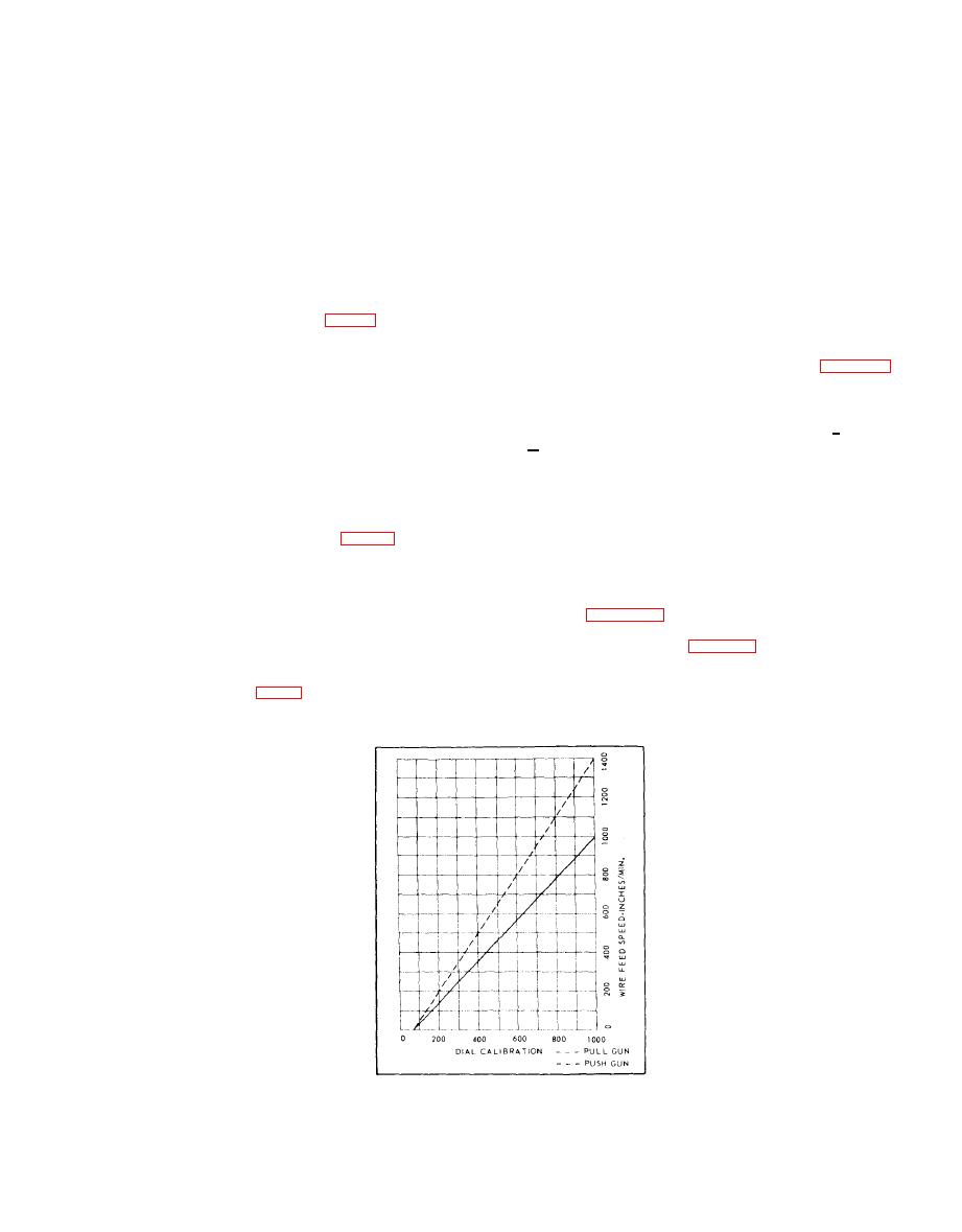
d . Measure output of wire fed from gun. Convert
t h i s to inches-per-minute.
a. Turn main power switch (Fig. 4) OFF.
b. Open Control door. Look for signs of overheat-
e. Check this output in inches-per-minute with op-
ing or burning of wiring or components.
t i m u m suggested by appropriate chart of Figure 10
c. Make sure tube and other plug-in parts are
for dial setting used in test.
secure.
d . Check that all cable and hose assemblies are
f . If output is less than optimum suggested, turn
tight.
Repeat steps a through
r h e o s t a t clockwise slightly.
e. Look for signs of physical damage inside or out-
e. If it is more, turn rheostat c o u n t e r c l o c k w i s e and
side of Control.
repeat operation.
4. 2.2 EVERY 60 DAYS
NOTE:
Calibration i s complete
when the actual wire o u t p u t speed
At least every 60 days, perform the following:
m a t c h e s the optimum suggested by
the charts.
a . Turn main power switch (Fig. 4) OFF. Open
Control door.
b . Wipe away dust, dirt, and grime. Use an air
4.4 TROUBLESHOOTING
hose, if necessary, to blow it out of Unit.
Whenever a malfunction occurs inthe welding system,
c . Tighten all loose wire connections. Repair or
r e f e r to Table III to determine whether the trouble
replace any wiring with damaged insulation.
d. Tighten all mounting hardware.
can be isolated to the Control. Troubleshoot the Con-
trol in accordance with Table IV.
4.3 CALIBRATING PROCEDURE
troubleshooting
Before
NOTE:
m a k e sure system has adequate in-
A calibration rheostat (Fig. 4) is provided in the Con-
let water pressure.
trol for calibrating the front-panel dial of the wire feed
F i g . 10 Calibration Charts
