
this voltage, it superimposes the electrical equivalent
relay contains an adjustable timer calibrated from 0
of wire feed speed. The resultant voltage is `applied,
t o 99. The program-section contains a circuit for a
through the saturable reactor, to the motor-run circuit
b r a k e solenoid (BD101) located in the feeder. This
which uses a thyratron to regulate the speed of the
releases an electro-mechanical brake on the wire
wire feed motor. Thus, the motor speeds up or slows
reel for pull guns. This section is also provided with
down, depending on the relation of its speed to that set
an input receptacle for an AIR SOMATIC spot acces-
on the dial. When the gun trigger switch is energized,
s o r y used for spot-welding,
The power input of the
t h e motor-run circuit is in a relay condition. This
s e c t i o n passes through the gun trigger and a water
pressure switch (SW104) factory-set at 25 psi, so that
p l a c e s the motor armature in series with the motor
field, Release of the trigger sets up a relay condition
even though the gun trigger is depressed, the Control
which places the armature in parallel with the field,
r e m a i n s inoperative if there is insufficient cooling
a n d in series with a 50-watt lamp so that dynamic
water in the system.
braking occurs, and the lamp glows. Hence, the lamp,
when lit, indicates a stand-by condition of the motor
3.8.2 SPEED CONTROL SECTION
(no wire feed). This is the same condition that exists
The speed control section electronically regulates
when only the main power switch (SW101) is turned ON.
the speed of the wire feed motor to produce the re-
quired wire feed speed. It contains a printed circuit
3.8.3 ELECTRIC BRAKE FOR WIRE REEL
board with a rectifier, amplifiers, voltage regulators,
resistors, capacitors, and a saturable reactor. These
c o m p r i s e a full-wave rectifier, a motor control cir-
In pull-type gun systems, the Control electrically re-
leases a brake in the Wire Feeder to prevent drag on
c u i t , and a motor-run circuit. The rectifier converts
the wire reel. When the gun trigger or jog switch is
input AC to filtered, regulated DC for the control cir-
energized, control relay CR103 or 104 in the Control
c u i t . The control circuit uses a dual triode to am-
plify the electrical equivalent of the motor speed from
a tachometer-generator on the wire feed motor. Onto
to release the brake on the wire reel hub.
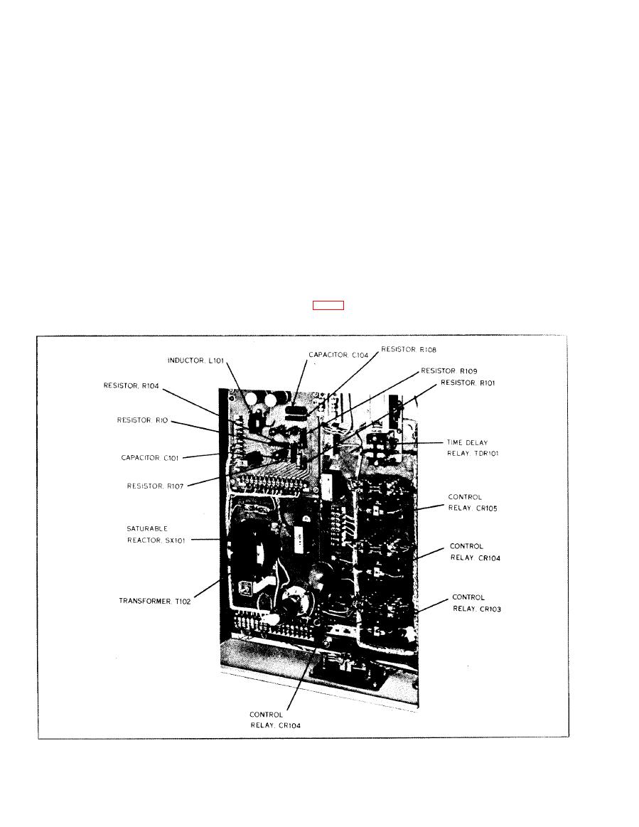
Fig. 9 Control Components
68
