
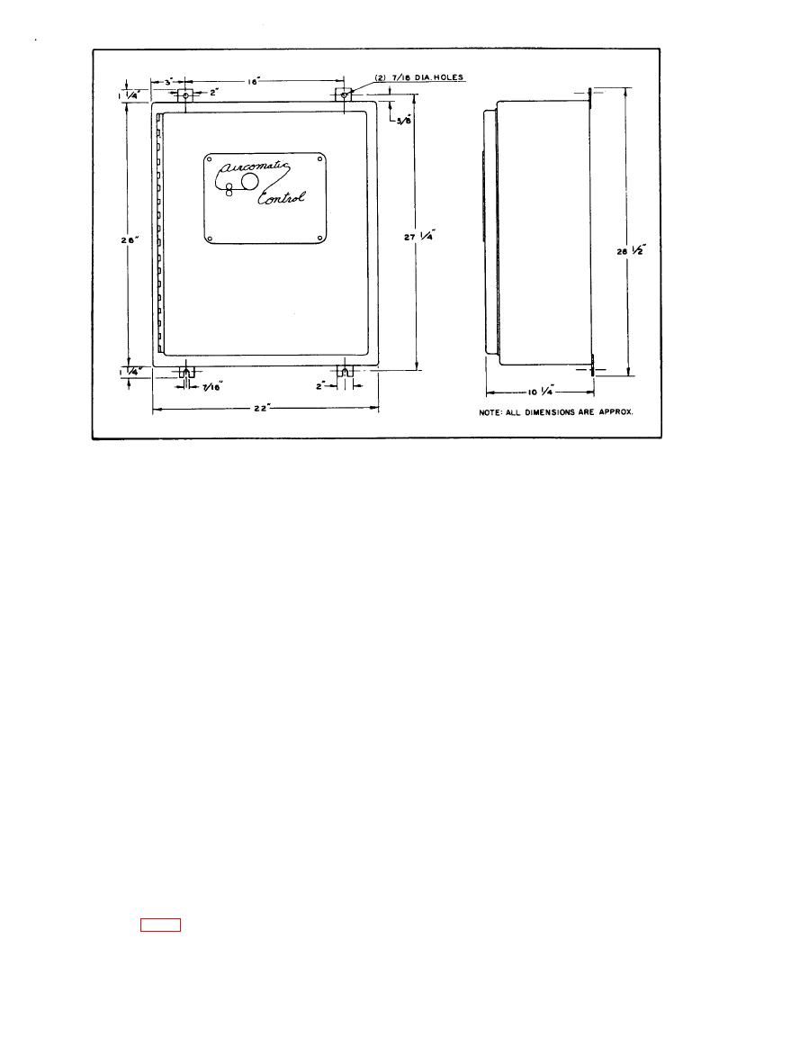
Fig. 2 Dimensions
contains a printed circuit board with a rectifier, am-
1.3 SUPPORTING EQUIPMENT
plifiers, voltage regulators, resistors, capacitors,
Supporting equipment includes other basic components
and a saturable reactor. These comprise a full-wave
which must be used in a system with the Control such
rectifier, a motor control circuit, and a motor-run
as an AIRCOMATIC push or pull welding gun and a
circuit.
Model AHF-E Push-Pull Wire Feeder.
1.2.2 OPERATING CONTROLS AND INDICATORS
The controls and indicators used for operation of the
Control are a main power switch, a power-ON indi-
cator lamp, a wire feed selector switch, a wire feed
calibration rheostat, and a rough-service lamp re -
sister.
Section Il. INSTALLATION
This section covers installation of the Control and
2.2 LOCATION AND MOUNTING
interconnection with all basic components needed for
the operation of an AIRCOMATIC welding system.
Choose a location for the Control that will have free
and easy access. Allow for complete opening of the
2.1 UNPACKING, INSPECTION AND ASSEMBLY
tinged door. Make certain there will be sufficient
Unpack the Control carefully so as not to damage any
space for connecting cables and hoses at the base,
parts or mar any finished surfaces. Check the en-
closure, both inside and out, for any signs of damage,
Unwrap the tubes and capacitors, and install these on
Secure the Control to a wood panel. Place it so that
the Control chassis (Fig. 3). Report any damage im-
the Power-ON lamp atop the Control will be at aver-
mediately to your nearest AIRCO representative.
age eye-line height.
