
c. Test.
(2) Connect an ohmmeter to the center termi-
nal and either outside terminal of the rheostat. Set
(1) Connect an Ammeter to the two outer
the meter on RX10 scale. Turn the rheostat in
terminals of the rheostat and set the meter on
either direction until it stops, then turn it in the
RX1 scale. The reading should be 5 ohms. If
opposite direction slowly and evenly until it stops
reading is more or less than 5 ohms, replace the
again. The indicator on the meter should increase
rheostat.
or decrease evenly according to the speed at which
(2) Connect an ohmmeter to the center termi-
the rheostat is `turned. If meter indicator does not
nal and either outside terminal of the rheostat. Set
function as described, replace the rheostat.
the meter on RX1 scale. Turn the rheostat in ei-
Note. Make sure that the ohmmeter used for the
ther direction until it stops, then turn it in the
above tests is in proper working condition.
opposite direction slowly and evenly until it stops
d. Installation.
again. The indicator on the meter should increase
or decrease evenly according to the speed at which
(1) Refer to figures 6-3 and 6-4 and install
the rheostat is turned. If meter indicator does not
the phase shift rheostat.
function as described, replace the rheostat,
(2) Install the right side shroud (para 3-13).
Note. Make sure that the ohmmeter used for the
above tests is in proper working condition.
6-6. Intensity Rheostat
d. Installation.
a. Removal.
(1) Refer to figures 6-3 and 6-4 and install
the intensity rheostat.
the intensity rheostat.
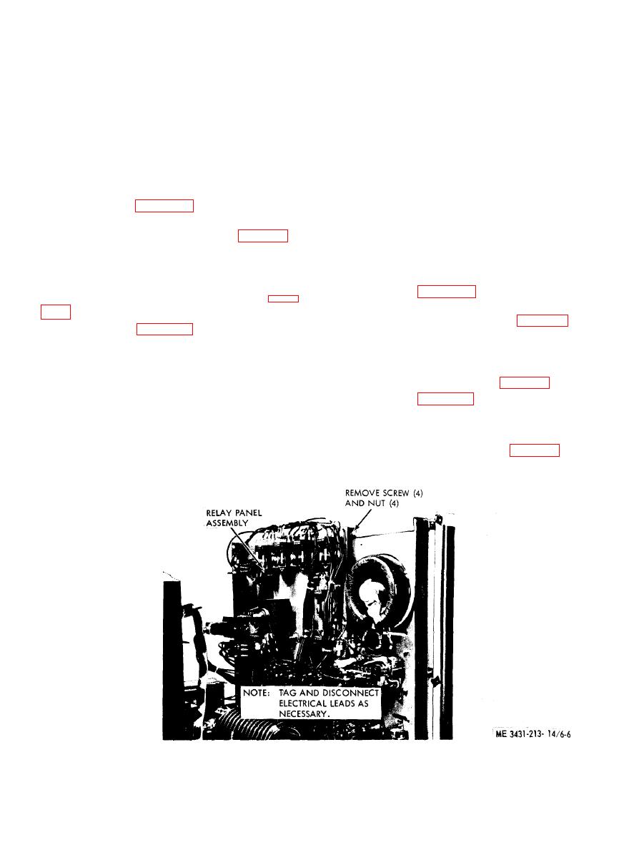
67. Relay Panel Assembly
b. Cleaning and Inspection.
a. Removal.
(1) Clean the intensity rheostat with a clean,
(1) Remove the side shrouds (para 3-13).
dry cloth.
(2) Refer to figures 6-5 and 6-6 and remove
(2) Inspect for breaks, cracks, corrosion, or
the relay panel assembly.
other damage.
b. Disassembly.
(3) Replace a defective intensity rheostat as
(1) Remove the control relays (para 6-15).
necessary.
Figure 6-6. Relay panel assembly, removal and installation, Model 2100H2007.
