
c. Test. Connect a suitable capacitor tester to
b. Cleaning and Inspection.
the wire leads and check the capacitors for open or
(1) Clean the rectifiers with a clean, dry
shorted circuit.
cloth.
d. Installation.
(2) Inspect for bent plates, bent or corroded
(1) Refer to figures 6-10 and 6-11 and install
terminals, or other damage.
the capacitors.
(3) Replace a defective or damaged rectifier
(2) Install the side shrouds (para 3-13).
as necessary.
c. Installation.
6-11. Resistors
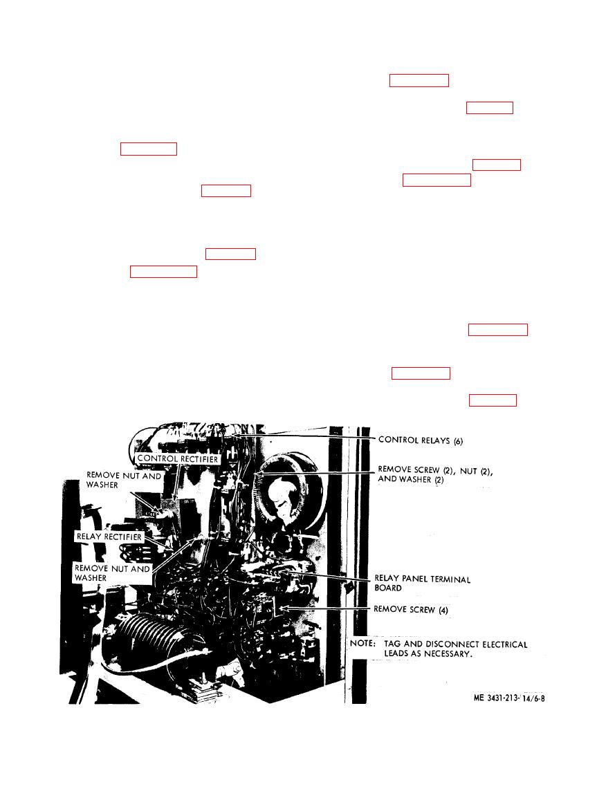
(1) Refer to figures 6-7 and 6-9 and install
a. Removal.
the control rectifier, the relay rectifier, and the
(1) Remove the side shrouds (para 3-13).
main power rectifier.
(2) Refer to figures 6-12 and 6-13 and
(2) Install the side shrouds (para 3-13).
remove the resistors.
b. Cleaning and Inspection.
6-10. Capacitors
(1) Clean the resistors with a clean, dry
cloth.
a. Removal.
(2) Inspect for cracks, breaks, corrosion, evi-
(1) Remove the side shrouds (para 3-13).
dence of heat, or other damage.
(2) Refer to figures 6-10 and 6-11 land
(3) Replace defective resistors as necessary.
remove the capacitors.
c. Test. Connect an ohmmeter to the resistor
b. Cleaning and Inspection.
leads and check the resistance. The meter reading
must conform with the resistor values listed on
(1) Clean the capacitors with a clean, dry
the schematic wiring diagram, figures 51 and
cloth.
5-2.
(2) Inspect for broken, corroded, or damaged
d. Installation.
leads. Check for signs of overheating or leakage in
electrolytic capacitors.
(1) Refer to figures 6-12 and 6-13 and install
the resistors.
(3) Replace a defective capacitor as neces-
sary.
(2) Install the side shrouds (para 3-13).
board, removal and installation, Model 2100H2007.
