
TM 1-4920-434-13&P
0063 00
REMOVAL CONTINUED
AIR FEED-THRU CONNECTOR ASSEMBLY CONTINUED
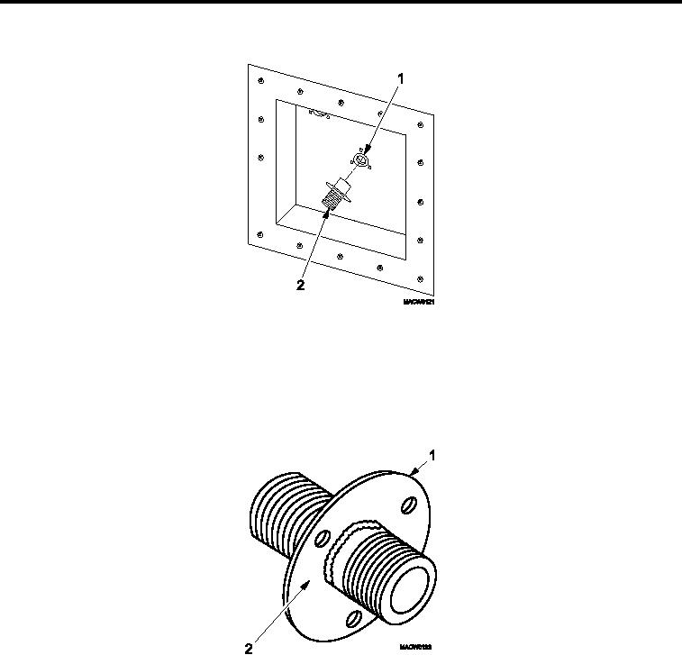
Figure 9.
Removal of Air Feed-thru Connector Assembly.
3.
Remove air feed-thru connector assembly (Figure 9, Item 2) from services utility panel.
4.
Remove old caulking compound (Figure 9, Item 1).
INSTALLATION
AIR FEED-THRU CONNECTOR ASSEMBLY
Figure 10.
Air Feed-thru Connector Assembly Flange.
1.
Apply caulking compound on inside of air feed-thru connector assembly lange (Figure 10, Item 2) toward
long end of air feed-thru connector assembly (Figure 10, Item 1).
0063 00-7