
helmet, gloves, welding cables, gas supply hose fittings
regulator and flowmeter, shielding gas, welding wire
a power source, and a secondary contactor if the power
source does not contain a primary contactor.
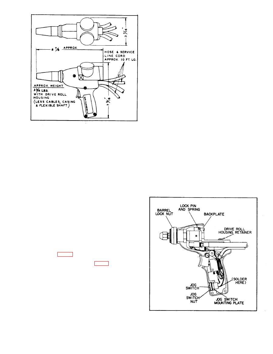
Figure 2. Dimensions
Section II. INSTALLATION
2.1 GENERAL
f. Lift left-hand handle off carefully.
This section covers installation of the Gun only, For
g. Remove plug near the handle bottom.
additional instructions refer to the applicable feeder,
control, and power source manuals.
h. Connect lead of jog switch to terminal on trig-
er switch which has two leads.
2.2 UNPACKING AND INSPECTION
Unpack the Gun carefully. Inspect the unit, cables,
and hoses. Operate the Gun trigger to make sure that
it is free. Inspect visible surfaces of the drive roll
housing for damage. Place the housing on the stripped
Gun. Inspect the casing assembly, liner, and outlet
guide bushing.
2.3 INSTALLING JOG SWITCH
NOTE: The Model AHF-E1 Feeder
includes a jog switch which may be
installed in the Gun handle as fol-
lows (Fig. 3):
a. Press down lock button (Fig. 4) on right side
of Gun and slide off drive roll housing.
b. Unscrew and remove nozzle from Gun.
c. Unscrew barrel lock nut.
d. Remove left screws from backplate and drive
roll housing retainer.
e. Lay Gun on its right side. Remove the four hex-
socket head cap screws which hold the left-hand han-
dle.
Figure 3. Installing Jog Button
