
TM 1-4920-434-13&P
OPERATOR INSTRUCTIONS
MACHINE AND WELDING SHOP
REMOVING LIGHTING
INITIAL SETUP:
Personnel Required
Tools and Special Tools
General Mechanics Tool Kit
CMF 15 Series (2)
(WP 0073 00, Table 2, Item 104 )
Equipment Condition
Functional
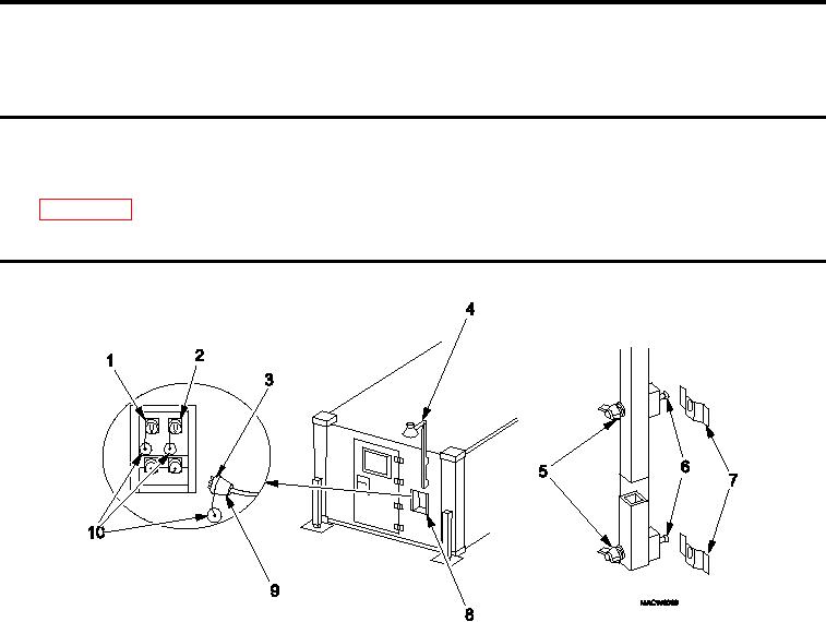
REMOVING AREA LIGHT
Figure 1.
Removing Area Light.
1.
Disconnect area light cable (Figure 1, Item 9) from either "J3" or "J4" connector (Figure 1, Item 1 or 2) on
power entry panel (Figure 1, Item 8) by loosening lock ring (Figure 1, Item 3).
2.
Replace protective dust cap (Figure 1, Item 10) on "J3" or "J4" connector (Figure 1, Item 1 or 2) on power
entry panel (Figure 1, Item 8).
3.
Replace protective dust cap (Figure 1, Item 10) on area light cable (Figure 1, Item 9).
NOTE
Do not remove wing nuts from screws.
4.
Loosen, do NOT remove, wing nuts (Figure 1, Item 5) and remove area light (Figure 1, Item 4) from location
outside shelter.
5.
Roll up area light cable (Figure 1, Item 9).
6.
Remove bulb and store in shelter BII box.
7.
Install area light (Figure 1, Item 4) on inside ixed personnel end wall by securing mounting screws (Figure 1,
Item 6) to mounting brackets (Figure 1, Item 7) and tightening wing nuts (Figure 1, Item 5).
0035 00-1