
KEY to figure 6-7.
(4) Remove screws (9); then remove end bell 123)
1. Screw
16.
(Protector
with assembled parts attached. Unsolder wires from
2. Plate
17.
Grommet
thermal protector (16); then remove thermal protector
3. Plate
18.
Nut
from end bell (23).
4. Label
I 9.
Washer
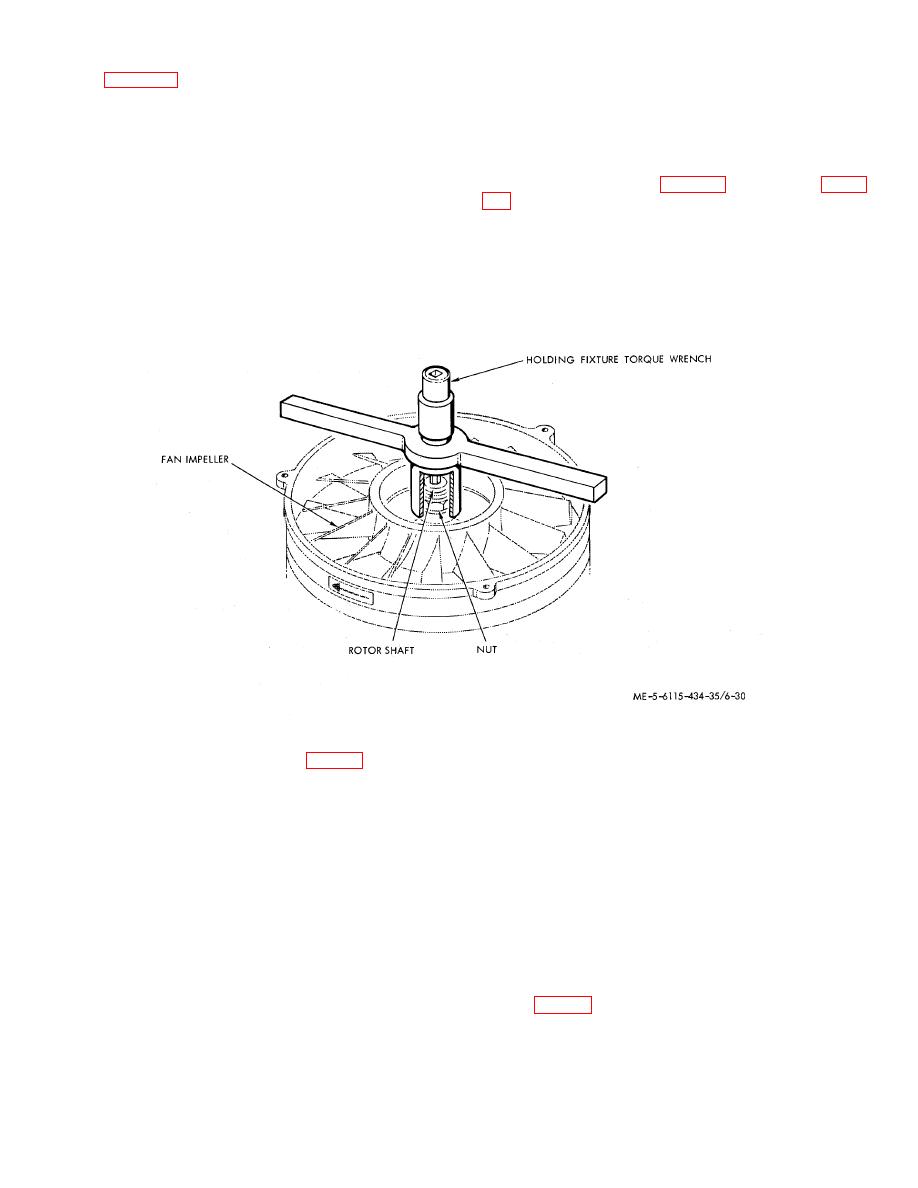
(5) Remove nut (18) using holding fixture torque
5. Connector
20.
Impeller
wrench (see Special Tools, table 2-1), as shown in figure
6. Bushing
21.
Screw
7. Bushing
22.
Plug
8. Bushing
23.
End bell
9. Screw
24.
End bell
10. Washer
25.
Bearing
11. Disc
26.
Rotor
12. Disc
27.
Housing assy
13. Disc
28.
Stator
14. Nut
29.
Insert
15. Screw
30.
Housing
Figure 6-8. Holding fixture torque wrench.
(6) Do not remove plugs (22, fig. 6-7) from end
(c) Wash all other parts in dry-cleaning
bell (23, 24) unless required after inspection.
solvent and dry thoroughly.
(7) Remove rotor (26}) from housing (27); then
(2) Inspection.
remove bearings (25) from rotor (26).
(a) Inspect all parts and wiring for damage.
(8) Do not remove stator (28) from housing
Check bearing surfaces; bearing surfaces must have no
(30).
discoloration indicative of overheating.
c. Cleaning, Inspection and Repair.
(b) Inspect all threaded parts for stripping or
(1) Cleaning.
cross-threading.
(a) Check thermal protector (16), rotor (26)
(i) Inspect plates (2, 3) and label (4) for
and stator (28) in housing (30) using a soft bristle brush.
legibility and for security of attachment.
Warning
(d) Inspect connector (5) for loose, bent, or
Varnish on stator (28) is soluble in
broken pins and for evidence of arc-over between pins
and shell.
solvent. Do not allow solvent to
(e) Connect thermal protector (16) to a test
contact stator. Use solvent in a
circuit (fig. 6-9) which monitors opening and closing of
well-ventilated area.
Avoid
the contacts, and check operation at the following
breathing fumes. Keep away from
temperatures.
flame.
(b) Clean exterior surface of housing (30)
with a clean, lintfree cloth moistened with an approved
cleaning solvent and dry thoroughly.
6-21

