
TM 1-4920-445-13&P
0002 00
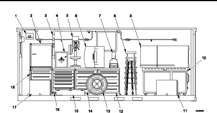
LOCATION AND DESCRIPTION OF MAJOR COMPONENTS CONTINUED
Item No. and Name
Item No. and Name
1. First Aid Kit and Bracket Assembly
10. Downdraft Table
2. Shelf Cabinet (A)
11. ECU (B)
3. Vacuum System Manifold Kit Assembly
12. Four Drawer Cabinet (D)
4. Flammable Storage Cabinet
13. Cable Reel Assembly and 60 amp Power
Cable Assembly
5. Upright Drilling Machine
14. Four Drawer Cabinet (C)
6. Eyewash Station Assembly
15. Shelter Basic Issue (BII) Box
7. Belt/Disc Sander
16. Six Drawer Cabinet (B)
8. Straight Stools (4)
17. ECU (A)
9. Mechanical Refrigerator Freezer
18. Four Drawer Cabinet (A)
Figure 5.
Fixed Wall Transport Mode Component View (1036059).
0002 00-5