
KEY to figure 10-2.
10-4. Compressed Air Hose Assembly and Vacuum
1.
Screw
4. Regulating valve
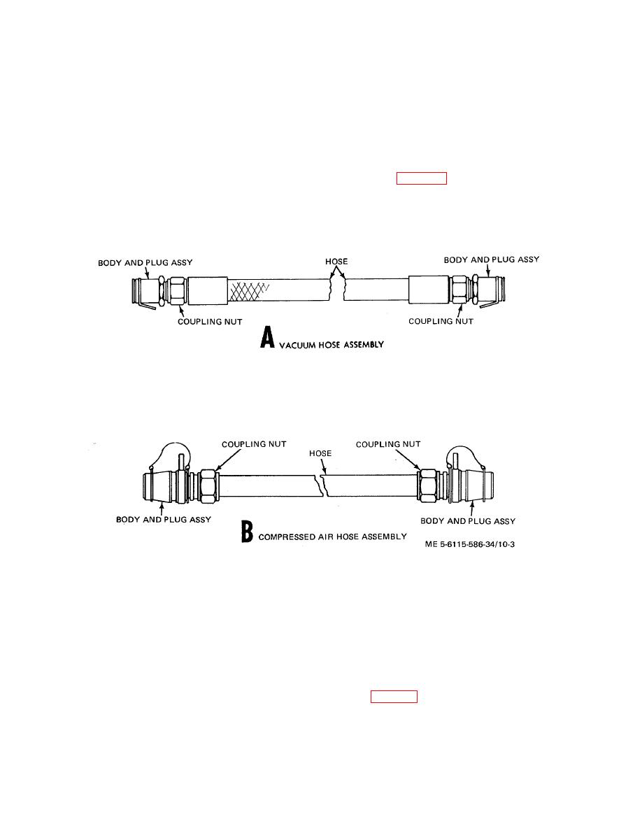
Hose Assembly
2.
Lockwasher
5.
Manifold cap
a.
General.' The compressed air hose assembly
3.
Flat washer
6.
Junction box
connects the inflation and deflation ejector assembly
(2)
Inspect the junction box (6. fig. 10-
to the power plant compressed air outlet. The vacuum
2) for bends and breaks. loose or missing latches or
hose assembly connects the power plant vacuum outlet
rivet nuts.
to elements of the MUST system that require vacuum
(3)
Visually inspect the two regulating
service.
valves for damage.
b.
Disassembly.
(4)
Test that regulating valves relieve at
(1)
Remove the two body and plug
1.5 -0.25 PSIG.
assemblies (fig. 10-3) from the compressed air hose
d.
Repair and Replacement. Replace all parts
ends by unscrewing them from the hose coupling nuts.
damaged beyond simple repair.
(2) Remove the body and plug assemblies
e.
Reassembly.
Reassemble the box and
from the vacuum hose ends by unscrewing them from
valve manifold assembly by reversing the disassembly
the hose coupling nuts.
sequence.
Figure 10-3. Compressed air hose assembly and vacuum hose assembly.
c.
Inspection. Inspect both hose assemblies
d.
Repair and Replacement.
Replace all
for any damage that could cause leakage, incorrect or
defective parts.
difficult connection of hose assemblies to fittings.
e.
Reassembly. Reassemble hose assemblies
by reversing disassembly procedure.
Section III. WATER SYSTEM ACCESSORY COMPONENTS
thermostatically-controlled electric heater that is
10-5. Dual Water Hose Assembly
powered from the power plant 400 Hz electrical system.
a.
General. The dual water hose assembly
b.
Disassembly. The dual water hose assembly
connects the hot and cold water outlets of the power
plant water system to other elements of the MUST
for repair as determined after inspection and
system.
The two hoses are heated by a
testing.
10-5

