
f. Installation. Install the wire harness assembly in
(2) Inspect for damaged or loose connector
pins, damaged wires, and loose or damaged terminal
reverse order of removal procedure. After installing
lugs. Check for any evidence of burned areas indicating
connector, safety wire in accordance with MS35540
shorts. Inspect connectors for damaged or stripped
using lockwire MS20995C20.
threads.
5-21.
AC Power Wire Harness Assembly
(13217E4158)
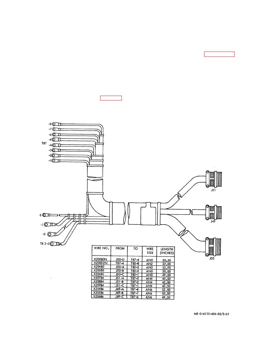
d. Testing. Refer to the wire run chart in figure 5-
2f) and check individual wires for continuity.
a. Removal.
Refer to figure 5-21; tag and
disconnect the AC power wire harness assembly as
e. Repair, Replacement and Reassembly.
follows:
(1) Solder connections will be made in
(1} Remove terminal board covers from
accordance with
MIL-S-6872
using solder Type
terminal boards (TB3 and TB7) and disconnect wire
SN60(!WRP2 per Fed Spec QQ-S-571.
leads to the boards.
(2) Replace defective wires with wire in
(2) Remove lockwire; disconnect connectors
accordance with MIL-W-5086, Type II. Wire size and
P49, P50, and P51; remove nuts, washers, and screws
approximate length in inches is provided in figure 5-2 0.
that attach connectors J49, J50, and J51; remove wire
harness.
(3) If self-clinching cable straps are removed
to) facilitate repairs, install new cable straps at two :,;l'
internals and at all cable breakouts.
Figure 5-21. AC power wire harness assembly.
5-28

