
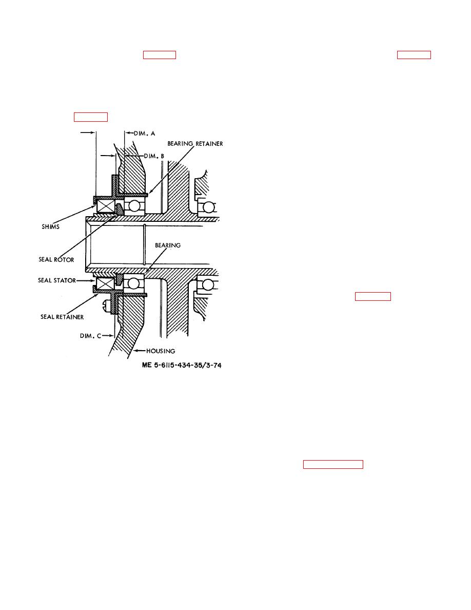
as required to obtain a dimension of 0.737 to 0.747 inch.
c. Determine shim requirements for seal (12) at
This is the required thickness of shims (13, fig. 3-13).
input end of gearshaft as follows (fig. 3-16).
d. Install amount of shims (13) determined above,
(1) Measure depth of retainer and record as
into retainer (11). Coat seal bore of retainer with one
dimension A.
coat of red Enamel (Glyptal No. 1201) and allow to dry.
(2) Measure height of lip on retainer and
Using arbor press and fixture, press seal (12) into
record as dimension B.
retainer (11).
(3) Measure from mounting flange of bearing
e. Install rotor of seal (12) onto gearshaft with
retainer to outer race of bearing and record as
dimension C (fig. 3-16).
chamfer next to bearing. Install key (8) and retainer nut
(7) onto gearshaft. Tighten retainer nut to 145 to 155
inch-pounds torque value., Bend key (8) into slot of
retainer nut. Install retainer ( 11) with seal (12) and
shims (13), assembled, into housing and secure with
screws (9) and washers (10). Tighten screw (9) to 40 to
60 inch-pounds.
f. Install new packing (17) into oil scavenge pump
(16). Install shaft (18) into the oil scavenge pump.
g. Install assembled scavenge pump into housing
and secure with bolts (14) and washers (15). Tighten
bolts (14) to 50 to 70 inch-pounds and lockwire in pairs.
h. Install reducer (6) into housing and install tee (5)
into reducer (6). Install caps (3, 4) onto tee (5).
i. Install packings (2) onto oil jets (1) and install oil
jets into housing assembly. Tighten oil jets to 40 to 60
inch-pounds.
3-14. Installation
a. Installation of Dual Pad Accessory Drive
Assembly.
(1) Install shaft (5, fig. 3-12, Sheet 1 of 2)
and gasket onto gearcase assembly (9).
(2) Install accessory drive (3) onto gearcase
assembly (81) and secure with nuts (1) and washers (2).
Tighten nuts to 100 to 110 inchpounds.
b. Installation of Generators. Refer to TM 56115-
586-12 for 60 Hz, 400 Hz generator installation
instructions.
Figure 3-16. Determining shim requirements for
input seal assembly.
(4) Subtract dimension B from dimension A
and add dimension C to the result. Add shim thickness
Section IV. ACCESSORY GEARCASE ASSEMBLY
3-15. General
3-16. Removal
The accessory gearcase assembly consists of a two-
a. Refer to TM 5-6115-586-12 and remove the 400
piece gearcase, a spur gear train, and accessory
Hz and 60 Hz generators.
mounting pads for the starter motor assembly, fuel
control unit, centrifugal switch assembly, oil pump
pad accessory drive assembly.
assembly, cooling fan assembly, and the dual pad
c. Refer to TM 5-6115-586-12 and remove the
accessory drive assembly that drives the 400 Hz and 60
accessory items: the starter motor assembly, the fuel
Hz generators. The accessory gearcase assembly is
control unit, the centrifugal switch assembly, the oil
driven by the gas turbine engine and the spur gear train
pump assembly, and the cooling fan assembly.
transmits the power to the various accessory items at
d. Remove the accessory gearcase assembly from
proper speed and direction of rotation.
the engine as follows:
3-30

