
MATERIAL USED IN CONJUNCTION WITH MAJOR ITEM
4-1. General
This chapter describes accessories, components, and
attachments used in conjunction with the welding
machine.
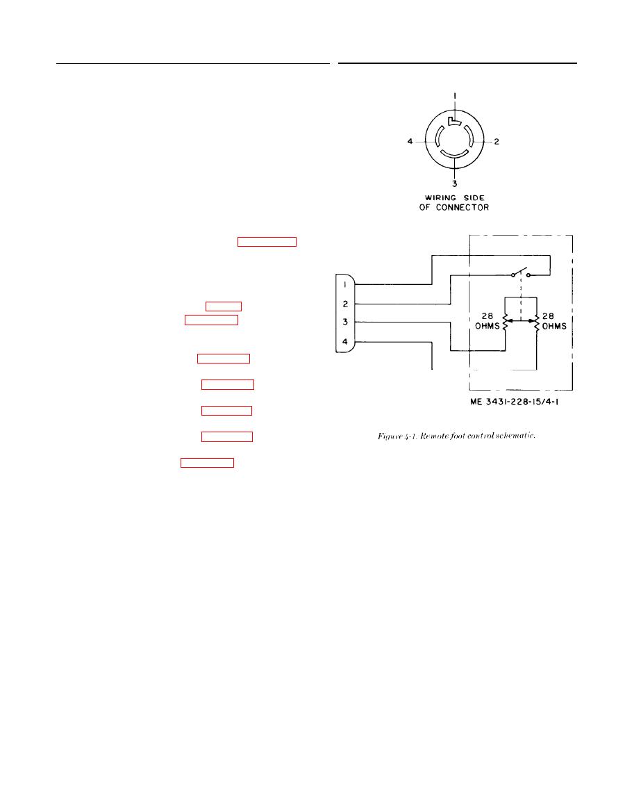
a. General. This accessory permits the operator to
operate the contactor and to vary welding current
with a foot control which may be located at the weld-
ing table. The foot control is attached to a cable,
which plugs into the REMOTE RECEPTACLE on
the front panel of the welding machine. The foot con-
trol contains a switch and a rheostat. Figure 4-1 is
the schematic diagram for troubleshooting or check-
ing w h e n required. The connector terminals are
identified on this illustration. For application in the
w e l d i n g machine, refer to the overall schematic
diagram of the welding machine (fig. 7-2).
the remote foot control case. Remove the four screws
and lift off the bottom of the case.
move the microswitch.
stall the microswitch.
move the rheostat,
stall the rheostat.
the foot control.

