
Figure 4. Wire Feeder, Inside View
NOTE: The adjustment knob, once
and out about an inch through the casing inlet guide
properly set, need not be readjusted
bushing housing (Fig. 6).
unless wire of different size or qual-
ity is to be threaded.
k. Release cam handle and gently turn adjustment
knob clockwise to add only sufficient pressure of
conical roll against wire to allow rolling friction for
1. Wind the spool counterclockwise to take up slack
feeding without deforming.
between the spool and drive rolls.
lMPORTANT:
1. Do not push wire back through the
drive rolls. The wire may kink.
2. If the wire end is not straight, cut
off the bent part and remove burrs to
prevent jamming in the casing.
m. Pass the end of the gun casing through the casing
retainer (Fig. 6).
n. Fit the casing through the drive roll housing near
the drive rolls so welding wire enters the end of the
casing inlet bushing.
o. Screw the retaining nut of the casing firmly into
the casing retainer.
p. Check that the casing inlet bushing is as close
to the drive rolls as possible without touching and
centered so wire cannot scrape against it. Align-
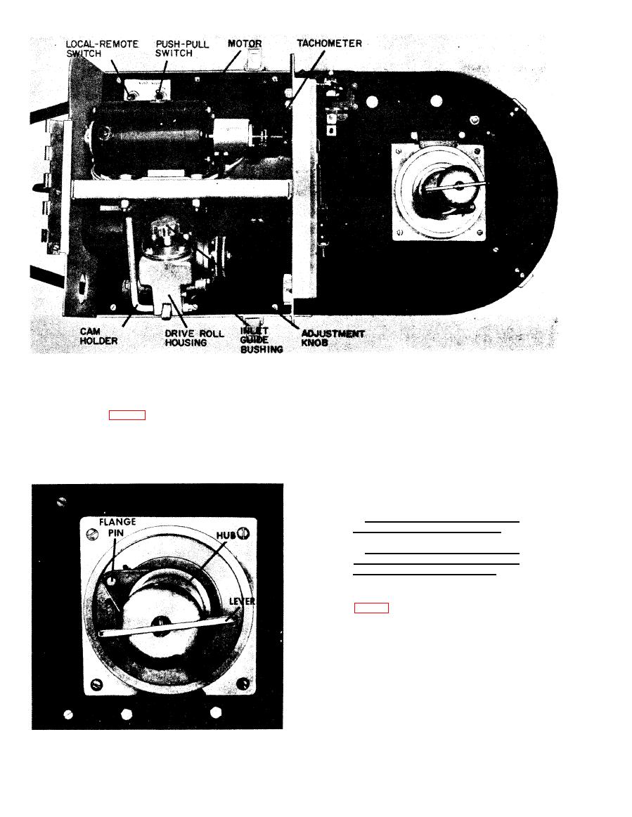
Figure 5. Hub Assembly
38

